back_to_main_menu

Switching power supply for ATLAS-210


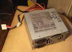
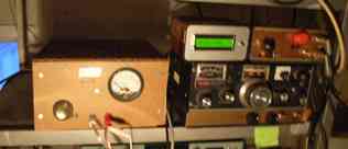
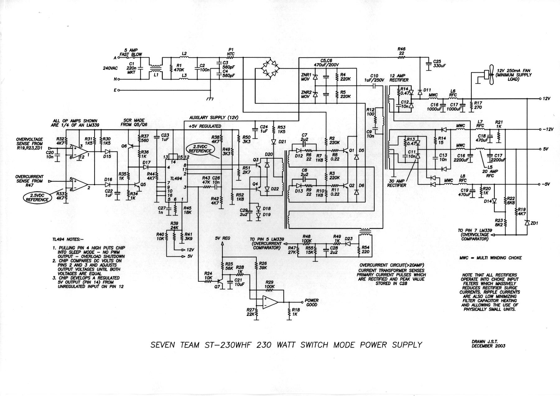
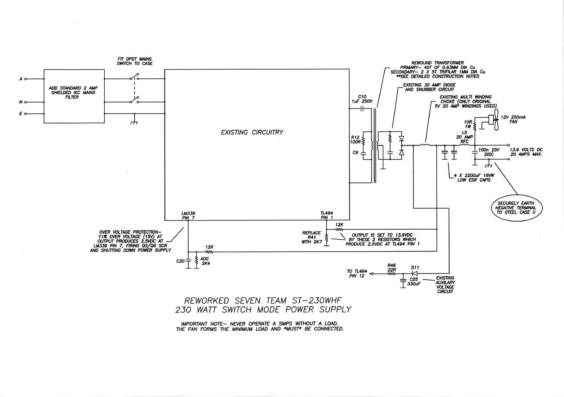
The idea is to use  a PC power supply to feed the ATLAS-210 .A typical PC power supply provides at least four DC voltage (+5 , +12 , -5 , -12 ) .ATLAS 210 is only asking for 13.8 volts with up to 16 amp (peak value) . Several descriptions appeared in various magazine like ELEKTOR (6/2003 issue)   and MEGAHERTZ MAGAZINE (march 2005 issue) .We prefered to follow the indications given  by F1LVT in the latter magazine (please refer to march 2005 issue page 24 to 29  ).

Nowadays it is still very easy to get surplus PC power supply for almost nothing  as an old PC is a waste that is even costly  to get rid of .

The first thing is to select a power supply giving a low level of HF signal in the 3.5 mhz band and rated  at least at 200 watt minimum .

 DO NOT TRY TO DO THIS MOD !!! IF YOU ARE NOT AWARE OF THE SHOCK RISK !!!

the starting power supply


You cut all wires coming out of the supply keeping only the various 12 volts wires which are soldered together and also 1 wire giving 5 volts  .

In order to boost the ouput voltage from 12 volt to 13.8 volt locate the Pulse Width Modulator which drives the switching  transistors .It is the brain of the supply !  Generally  it is a small digital circuit  (reference TL 494 or something  else ending with 494)   having 16 pins .To get full details about the TL494 circuit  see the following link TL494 datasheet ) .There is various circuit equivalent to the TL494 like HA17339, and the KIA494, KA7500, IR3M02, and MB3759 . To increase the output voltage  you only have to put a resistor between pin 1 and 7  .The value has to be adjusted in order to get the 13.8 volts at the output .(the value is between 10 and 20 Kohms ) .It should be noted  that for some power supply ,to have  a good regulation of the output , it is necesary to load the 5 volt circuit  with a resistor in order to have some current anywhere between 0.5 and 1 amp .

To get a reading of  the output voltage with a good sensivity it is a good practice to measure it with a meter in serie with a zener diode of 10  or 12 volts and a resistor so to have a scale starting at 10 or 12 volt and ending at 15 volts .It is also a good idea to put an AMP meter (0 to 20 amp on the ouput  .You put everything in a box .You are all set !


Get full diagramm of standard switching power supply


the pulse width modulator circuit

Four power supply where done according to this design  and they operate without any problem on 2 ATLAS-210 and two  VHF / UHF transceivers .No problems of QRN or QRM due to the power supply  on any band even on 3.5 mhz  .Keep on going . Atlas-210 with its power supply


On some recovered power supply you can be bothered by some small birdies , which are harmonics of the frequency used by the power supply .This can be observed mainly on the low bands (3.5 mhz) .Generally on that band the noise signal is quite high  and this is not a problem .However if it is not the case  and if the signal of your fellow contact is not very strong  and if  his signal is right on the harmonic  this can be annoying .That is why  it is a good idea to put  a QRN SHIFTER  .THis is a  quite simple add on .It consists of a simple resistor which is put in parallel of the existng resistor R16 (see the following diagram) .THis resistor in conjunction with C11 capacitor defines the working frequency of  the power supply .If you add through a switch a resistor in the 47 k range you will be able to shift the frequency to clear the frequency that you are listening either on 3.5 or 7 mhz band .TL494 circuit the heart of the power supply

Detailed view of the regulator circuit of a typical switching power supply

================================================================================================
This is not the only way to get 13.8 volt from a regular PC power supply .As you have seen there are various description of modification on the internet . Please find some we have discovered , this list is not limited !and will grow in the future
Another schematic for a PC power supply

The mod to output 13.8 volts

=======================================
Another schematic with the modification


ANOTHER WAY TO BOOST VOLTAGE TO 13.8 Volt

Nowadays (as of april 2010) it becomes easy to get for free  more modern PC power supply beeing able  to deliver more power  with better regulation using more sophisticated .Pulse width modulator  than the standard TL494 or its various equivalents .For example  the LC-B400 ATX is such a  power supply .Three of them were recovered in goof shapelc-B400 ATX external view


Based on what was written on the cabinet  they are able to deliver 12 volts with 17 amps  , 3.3 v with 28 amp and 5 volts under 40 amps .Surprisingly it is very easy to modify these power supply to make them being able to deliver 20 amps under 13.8 volts as needed for your ATLAS 210 .
lc-b400 atx aerial view


The principle used to increase the output of the power supply is to alter the voltage taken by th Pulse Width Modulaor to keep voltage constant for whatever  power .This is possible by inserting a small resitor in the feed back loop  going from the 5 volt ouput to the Pulse Width Modulator .

Open the power supply and remove the circuit board to find the trace going from the 5 volt output to the pulse with modulator labeled 2003 IFFASK...... (the exact label varying from power supply to other power supply of almost the same type )
lc-b400 schematic before


LC-B400 ATX Schematic before modification


Cut the trace as indicated on the schematic .Insert a 1/2 watt 47 ohm resistor .That is all ..Now the power supply deliver 13.7 volts on the 12 volts output .The regulation is very good the voltage output being only reduced by 0.2 volt when the current vary from  100 milliamp to 20 amp (full load of the ATLAS 210 ) .The modifications were done on the 3 power supply with the same good results .It should be noted that  the circuit board was not exactly the same on one of the supply .If the link  between the 5 volt output to the 3.3 volt through 2 silicon diodes in serie and a 0.7 ohm resistor does not exist it should be implemented to obtain the desired resultlc-b400 ATX schematic after

LC-B400 ATX Schematic after modification


Back to main menu