| If you want to use your ATLAS 2210 at
its top level you will need sooner or later a wattmeter to finely
adjust its various circuits .When you can buy a vintage ATLAS210 from
150 US $ up to 250 $ depending on its state there is no reason to
put several time more in buying a fine but very expansive
equipment like a BIRD wattmeter .You can easily build your own
appartus as you will see . |
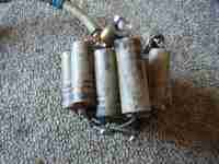
The
first thing is to make a dummy load using non inductive resistors .The
maximum output of ATLAS being in the range of 80 watts under a 50 ohm
impedance you will have to solder in parallel the needed number
of resistors so to have 50 ohms .In my own design i decided to use 17
resistors each having on average a value of 1000 ohm .The total
resistance is 60 ohms not far from the theoritical value of 50 ohms .
Each resistor is able to dissipate around 3 watts of heat and therefore
the dummy load is able to run at the 50 watts output level on a
continuous manner and at 100 watts for a few minutes .By just putting
your fingers on the resistor you can know when it is time to stop
tuning your rig so as to not overheat the resistors . |
|
 |
 |
|
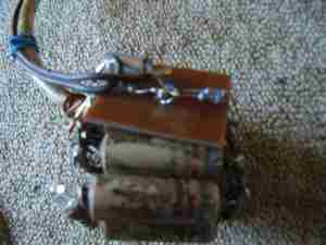
| To
visualize the HF current flowing into the dummy load the simplest way
is to put in series with one of the resistor a small light bulb .You
choose a model being able to run at a few volts with a 0.1
ampere current .Just by looking at the light bulb you are
able to have a rough idea of the output power . |
| If you want to have better precision the best way is to measure the HF voltage found across the dummy load .The schematic is shown .In parallel with the resistor you put a voltage divider so as to divide by 10 the voltage (combination of a 18 k + 2 k resistor ) .This voltage is rectified with a schottky diode (BAT 41) , the continuous voltage obtained being the peak voltage of the HF current .This voltage is measured using any voltmeter | 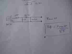 |
|
| TO
know what is the output power you applied the well known formula
: P=U*U/R (as you measure not U but U max the value that you
measure has to be divided by 1.414 to get the the U used in the formula
) .To prevent the capacitve coupling between the voltage divider and
the dummy load it is a good idea to solder a metal plate in between . |
||
| You can also put the voltage divider and the schottky diode directly on a BNC socket and insert the device using a T coupling in the line going from your ATLAS210 to the dummy load .The set up is quite simple as shown hereunder .The voltmeter used to measure the continuous voltage should have an internal resistance high enough .Compare to professional wattmeter the result is within the 10% range | 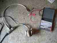 |
Back to main menu