ATLAS 210 BROADCASTER
| This is a very simple device allowing you to transmit what your ATLAS 210 is receiving in another place .There is a several case where this device is useful .For example it is winter time , your shack is located beneath the roof , outside temperature is in the 0 deg Celsisus range and it is almost as cold in your station and you want to hear a QSO . If you have not the BROADCASTER the only way to hear the QSO is to spend several minutes in a cold environment with the risk of catching a bronchitis or even something more terrible . .If you own a BROADCASTER you only have to switch on your transceiver ATLAS and the BROADCASTER and go in the living room , hearing the qso on your FM receiver .This is not the only way to use the BROADCASTER .Another very useful usage is to retransmit directly on your car receiver all the songs your have in your MP3 player by directly feeding the BROADACASTER with the audio coming out of the MP3 player . | |
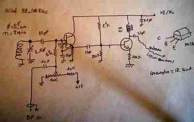
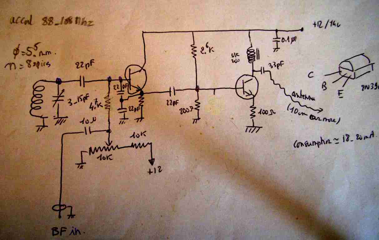
| THE SCHEMATIC It is outlined on the right . The BROADCASTER is a low power transmitter operating in the FM band anywhere between 88 and 108 mhz so as to be received with any commercial FM receiver .The design of the BROADCASTER is very simple .It uses 2 transistors (2N3904 ) , the first one operates as an oscillator controlled by an LC circuit , the second one is a buffer and an amplifier .It can be fed with a power supply of 12 to 14 volts .The total consumption is around 20 mA . The oscillator coil has 8 rounds on 5.5 mm diameter .The polarisation of the oscillator is adjusted by a variable potentiometer .The frequency modulation is created by directly feeding the oscillator with the audio signal to transmit . Full size schematic |
 |
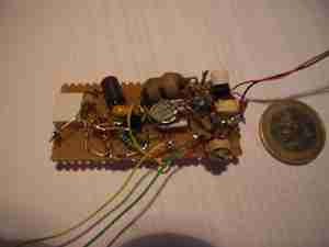
| HOW TO BUILD THE BROADCASTER The BROADCASTER , thanks to its simplicity , can be directly build on a piece of perforated copper clad .The various components needed are outlined on the schematic (full size) The only adjustment to be made after checking that the wiring has no mistake is adjusting the potentiometer so as to have a curent between 10 and 20 ma (under 12 volt supply .The antenna used to radiate the HF power can be any length from 10 to 80 centimers |
 |
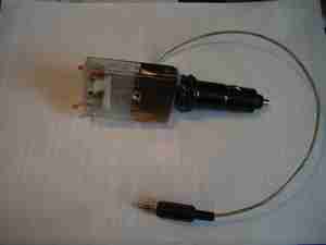
| SET UP AND OPERATION The full circuit can find its place in a small plastic box .For convenience especially if you use it in your car the box can be glued on a sandard plug as shown on the left . A small LED is also added to visualized when power is applied .When used is a car there is no need to put an external antenna as the signal is strong enough even compared to other FM radio stations on the band .If you want to send up to 100 meter it is better to use a piece of wire as antenna .The length is not critical . Back to main menu |
 |