| Nowadays
due to the ever growing number of radio stations in the FM
band (between 88 and 108 mhz) it is more and more difficult to
find
the radio station you want to listen .On top of that you want to
listen
different radio stations dependig on the time of the day ,
surprinsingly It is not easy to find a receiver being able to switch
automatically from different frequencies according to the time.Thanks
to microcontroller and arduino it is not difficult to revamp an old FM
receiver to do the job | |
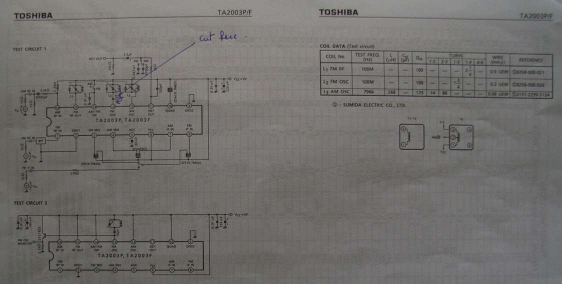
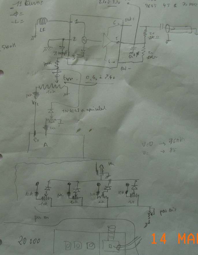
| The schematic of the receiver to revamp | |
| You have to locate the IC which is doing the frequency conversion .In our case it was a TA2003 from Toshiba .You have to cut the trace as indicatde above so to be able to control the local frequency from an oscillator that will be set up . |
| The local oscillator can use one transistor followed by another one which acts as a buffer .You will have to build as many oscillators as you want to receive radio station .Each oscillator is fed by the microcontroler | 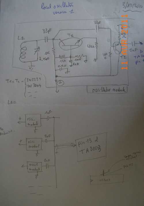 |
| The design can be quite compact as shown and it worked .! However to stay on line with the various integrated circuits available on the market we switched to an integrated oscillator much more compact and which only need a coil to produce a signal anywhere in the 50 to 600 mhz range | 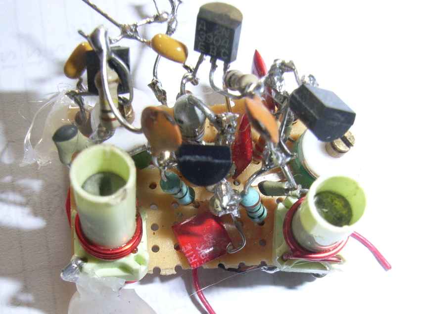 |
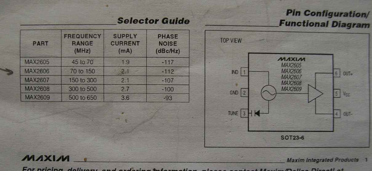
| The oscillator use an integrated circuit from MAXIM , the max 2606 .This circuit is able to operate from 70 to 150 mhz which is perfect for our case .The intermediate frequency being around 10 mhz the oscillator has to work from 78 to 95 mhz or from98 to 125 mhz .It is up to you to choose . | |
 |
| You will have to put as many potentiometer s that the number of channel you want to listen .Let's say you want to listen 3 FM radio stations you put 3 potentiometers .To cover the full range given by Maxim the voltage has to go from 0.4 volt up to 2.4 volts | |
 | T |
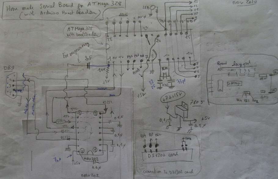
| The control of the various oscillators is done by the arduino according to the schematic below .It is a complete board being linked to the external world through a standard RS232 interaface (DB9) .an ATMEGA 328 with the Arduino bootloader is more than enough .The arduino receives time information from a DS1302 circuit and it remains 9 pins to connect as many potentiometers .You will notice the 2nF capacitor and the 10k resistor going on pin 1 of ATMEG328 this set up enabling the capability to program the arduino using the standard procedure thanks to the DTR sigal taken the th DB9 connector | |
 |
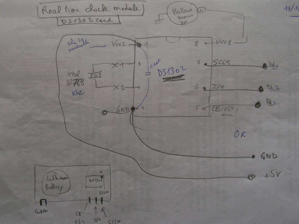
| The real time clock schematic is very standard and use a DS1302 according to outline below .A lithium battery keep the circuit working when no power is available | |
 |
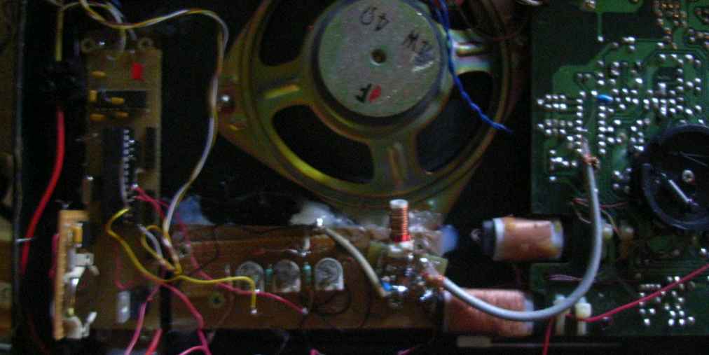
| Everything
is done on a veroboard circuit and packed inside the radio
receiver being revamped as shown on the photo below .There
is no problem to find a room in these old reveiver ! .On the left of
the image you see the arduino board with the DS1302 real time clock
.In th bottom of the image the oscillaor board with the
MAX2606 appear .The ouput of this circuit is sent directement through a
small coax to the Toshiba TA2003 | |
 |
| Ok
when al is done you will have to adjust the different channels
you want to listen by adjusting the different potentiometers .When this
is done programming the arduino is the last thing to
do . AN example of program is shown below in our case where we wanted to listen 3 channels switching from one to another at various time of the day .Thanks to the possibility of arduino board you can program much more complicated schedule ! .The program take advantage of the DS1302 library which has to de downloaded from the link indicated on top of the program it should be noted that a manual command has been implemented using a potentiomer linked to pin 0 .Depending on the analog value read the receiver is tuned on each of the selected channel and can stay as long as you want or switch automatically depending on the action take by the program |
| /* DS1302_Serial_Easy (C)2010 Henning Karlsen web: http://www.henningkarlsen.com/electronics */ // I assume you know how to connect the DS1302. // DS1302: CE pin -> Arduino Digital 2 // I/O pin -> Arduino Digital 3 // SCLK pin -> Arduino Digital 4 // revision 10/12/2010, 16/12/2010 ,17/12/2010,26/12/2010 // 13/3/2011 #include <DS1302.h> DS1302 rtc(2, 3, 4); // Init the DS1302 Time t; // Init a Time-data structure // variables will change: // radio channel assignement #define n_radio_station 4 // number of radio stations #define france_culture 13 // name of station , pin number #define radio_classic 12 #define france_inter 10 // name of station , pin number #define bfm 11 #define first_canal 13 // pin use for first channel // command buttons # define analogInPin 0 // pin used for manual control using a potentiometer int sector_value=1024/(n_radio_station+1); // other variables char* instant; int xx; int heure ,minute ; int sensorValue = 0; // value read from the pot int channel_to_activate,previous_channel; void setup() { pinMode(france_inter,OUTPUT); pinMode(france_culture,OUTPUT); pinMode(radio_classic,OUTPUT); pinMode(bfm,OUTPUT); // Set the clock to run-mode, and disable the write protection rtc.halt(false); rtc.writeProtect(false); // set charging supercap rtc.setTCR(TCR_D1R4K); // Setup Serial connection Serial.begin(9600); // The following lines can be commented out to use the values already stored in the DS1302 //rtc.setDOW(FRIDAY); // Set Day-of-Week to FRIDAY //rtc.setTime(12, 0, 0); // Set the time to 12:00:00 (24hr format) //rtc.setDate(6, 8, 2010); // Set the date to August 6th, 2010 } void loop(){ sensorValue = analogRead(analogInPin); sensorValue=sensorValue/sector_value; // sensorValue vary now from 0 to 3 for 4 radio station Serial.print("sensor value="); Serial.println(sensorValue); //delay(1000); if (sensorValue==0) // case of atomatic mode { instant=rtc.getTimeStr(); Serial.println(instant);// Send time t=rtc.getTime(); heure=t.hour; minute=t.min; // Serial.println(heure,DEC); //********************************************************************************* // to be modified depending on radio station to listen //check_channel(france_inter,2,0,3,10); // name of fm radio station ,start hour start minute,min depart , h end minute end check_channel(radio_classic,6,30,7,30); check_channel(france_culture,7,30,8,0); check_channel(bfm,8,0,8,30); check_channel(france_culture,8,30,12,30); check_channel(radio_classic,12,30,13,0); check_channel(france_culture,13,00,15,0); check_channel(radio_classic,15,0,17,0); check_channel(france_culture,17,0,22,00); //check_channel(bfm,8,0,12,0); activate_channel(); // *********************************************************************************** delay (1000);// Wait one second before repeating :) } else // case of manual mode { select_channel(france_inter,sensorValue);// activate the channel selected by the potentiometer select_channel(france_culture,sensorValue); select_channel(radio_classic,sensorValue); select_channel(bfm,sensorValue); } } //********************************************************************************* void check_channel(int canal,int h_depart,int m_depart,int h_fin, int m_fin){ int hdepart,hfin,hactu; hfin=60*h_fin+m_fin; hactu=60*heure+minute; // hdepart=60*h_depart+m_depart; if (hactu>=hdepart && hactu<=hfin ) { //Serial.print(canal); //Serial.println(" actif"); channel_to_activate=canal; } else { //Serial.print(canal); //Serial.println(" non actif"); } } //********************************************** void activate_channel() {if (previous_channel!=channel_to_activate) {digitalWrite(previous_channel,LOW); previous_channel=channel_to_activate; } digitalWrite(channel_to_activate, HIGH); Serial.print(channel_to_activate); Serial.println(" est actif"); } //*********************************************************************** void select_channel(int canal,int i){ int j; //Serial.println("active en manu" ); j=first_canal-canal+1; //Serial.print("canal /i ");Serial.print(j);Serial.print("/");Serial.println(i); if (j==i){ digitalWrite(canal, HIGH); //Serial.println ("canal active "); } else{ digitalWrite(canal, LOW); } // delay(1000); } |