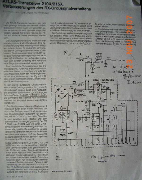
You will have to operate on the PC100 board to insert the amplifier as stated nearby
| The sensivity of the receiving section of your ATLAS 210 is not as high as it is with modern transceiver .This is not a problem when operating on the low bands (3.5 and 7 mhz) where the real limiting factor is the band noise .However on 14 mhz , 21 mhz and 28 mhz band where noise is not as high it is obvious that something has to be done to boost the received signal .One thing is to change the mixing diodes and replace the silicium diodes by Schottky diode (BAT 85 or others (click here how to do)) .Another action is to put an HF amplifier working only on the high bands . Several descriptions have been done in the amateur radio litterature .We will describe here only 2 modifications : one realized by ourself and another one described in the CD-DL Journal (october 1985 issue ) | |
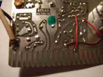
| WHere to put the HF amplifier : You will have to operate on the PC100 board to insert the amplifier as stated nearby | |
| To made the modification you only have to cut a copper line on the PC 100 printed circuit and to use 2 pieces of small diameter coax to link the amplifierto the modified board as shown on the schematic above | |
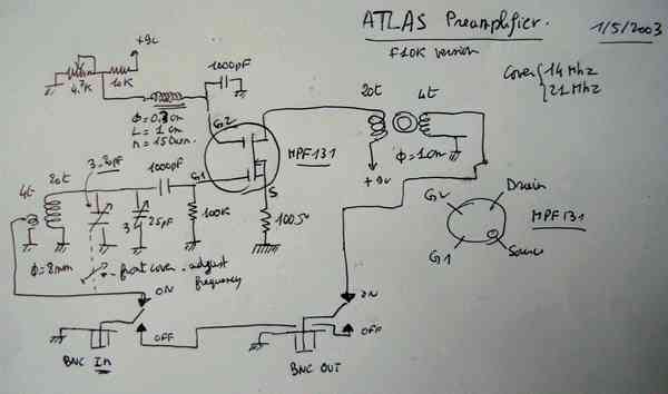
| F1OK HF amplifier It is based on a standard design using a dual gate mosfet . MPF 131 was choosen but other type can also be used depending on what is avalaible in your shack . ..The sensitivity is adjustable by variation of the tension ont the gate G2 .The maximum HF gain is around 20 db which is more than enough .The tuning circuit in the front end cover easily the 14 and 21 mhz band .THee is 2 adjustable capacitors .One is inside the other is adjustable from the outside by the opertor .The amplified signal is send to the ATLAS 210 through an HF transformer A double 2 positions switch is used to put in service or out of service the amplifier | 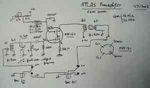 Bigger schematic XXL schematic |
The amplifier is working on rechargeable batteries because the amplifier is located in a box outside the ATLAS .The consumption is in the 5 ma range | 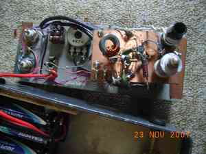 |
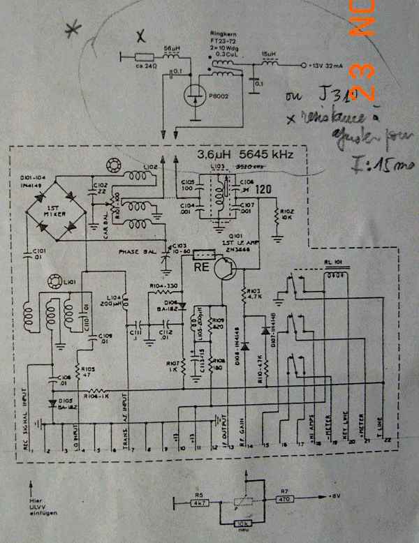
| DL1BT AMPLIFIER It appeared in the october issue of CQ-DL journal .Thanks to F3UE , a french ATLAS 210 GOUROU , we were able to have a copy of the article which is hard to find nowadays .It should be noted that the amplifier is working on the Intermediate Frequency . Two types of transistors can be used as shown in the diagram nearby .F3UE check the first design replacing the P8002 fet transistor by a J310 adjusting the resistor to have a 15 mA current and was very pleased by the results Get a copy of the article in german | 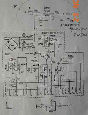 Bigger schematic |
| Another design outlined in the same article is possible using regular NPN transistor (2N5109 ) but amplifying the HF incoming signal and not the intermediate frequency | 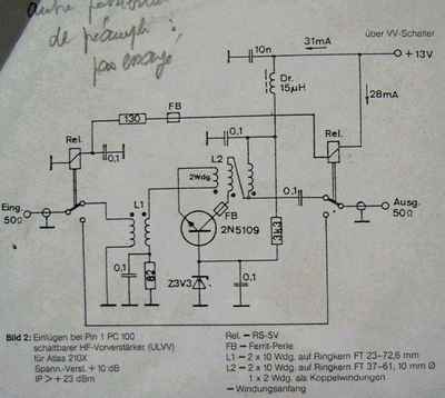 |