
| As
you probably know energy is becoming more and more scarce and
expansive and the only way to cope with this is to use as less energy
as possible .For ham radio operators this means to use less power
for their transmitter .This is a new challenge .It is quite easy using
your standard rig to contact anybody around the world with 100 watt of
input power either in SSB or digital mode but this is a different story
with transmitter below the 1 watt mark .There is many awards around the
globe to promote such operations (for example the MILLIWATT
PER KM AWARD ) .With your Atlas it is not easy to make it working under
the 1 watt level , and that why it is better to build a new transmitter
using the ATLAS just for receiving as in the receive position the ATLAS
is very efficient , consuming much less power than new rig . | |
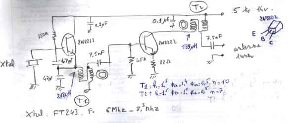
| The scheme of the rig is outlined nearby .It is very simple and use junk parts recovered from old computer and tv set .It need 2 transistors (2N2222) .The frequency is defined by a quartz crystal (FT243 or other) The output power depends on the voltage which can be anywhere from 5 volts up to 14 volts . In order to reduce the input power at the lowest level possible CW is use to modulate the carrier .The output is send to a standard antenna tuner and the antenna .Needles to say that the antenna as to be a good one that means at least a full size dipole located 1/4Lambda above the ground | 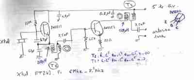 get bigger display of schematic |
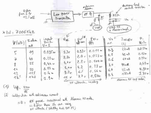 | There is no tuning circuit and the tx works anywhere between 3 to 21 mhz depending on the quartz crystal used .The output is directly related to the power voltage from 5 to 14 volts . |
| The transmitter as described enable me to break the 1 milliwatt/km
barrier on 7 mhz band .Ok this is not a big deal but not so esay to
achieve especially in early 2008 at the lowest part of solar cycle 23
.It is also used to transmit routinely once per day various data over a
600 km link , the transmitter being fed with solar cells and controled
with a microcontroller (Basic Stamp from Parallax Inc) | 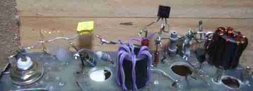 |
| As
of the mid of 2010 the Basic stamp set up used to control
the transmitter was revisited to take advantage of newer
microcontrollers .The objective was to follow the variation of
propagation on the 3.5 mhz band over a 600 km path using the
transmitter shown above on a 24 hour a day basis.The power supply of
the transmitter was no longer a solar panel + a Li Ion
battery but a phone line feeding the battery .Unfortunatly the
phone company does not supply for free an unlimited current .The
maximum amperage which can be taken without disrupting the normal use
of the phone line is limited to 4 mA (if you try to draw more , the
phone line is no longer available for incoming calls ! ) .This
amount is fixed by simply using a resistor between the phone line
and the battery . In order to match the energy available and the power
needed by the transmitter the transmitter operate automaticly from time
to time .The basic stamp controller was change an a picaxe 08M
was selected to do the job .There was several adavantage in doing so
.The price of picaxe 08M is cheap (around 2 US$ in single quantity) ,
It can be programmed using a very simple IDE using BASIC
language On top the electric consumption of the picaxe 08M
can be very low thanks to its SLEEP mode .By putting on high
state all the unused ouput and bridging to ground the unused input
the electric consumption reach the 5 microamps level in sleep
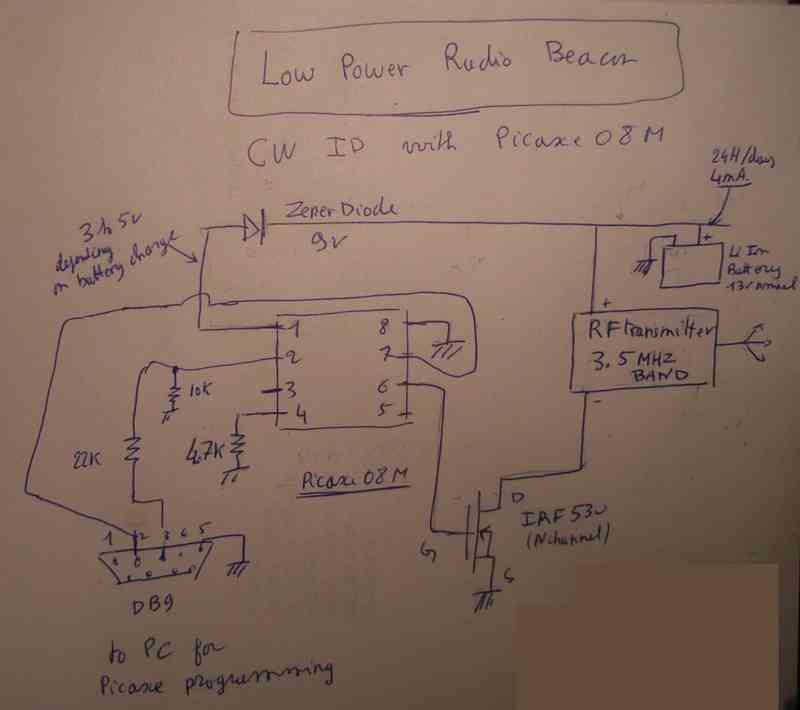
mode .The schematic is shown here .The transmitter is keyed
through a power mosfet (IRF530) ./The picaxe 08 which is able to
operate with a power suply from 3 volts up to 5.5 volts is fed
from the general power supply (13 volt) with a 9 volts zener diode in
serie .It can be programmed directly in place using a standard RS232
linked to a PC | 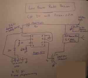 Get a bigger schematic The program to control the transmitter : ;************************************* 'beacon control using Picaxe 08M ' consumption in sleep mode 3 microamp high 4 high 2 ; in3 linked to gnd through 4.7 k to reduce current in sleep ;********************************** main: disablebod sleep 20 gosub beacon goto main ;************************************ beacon: high 1 pause 1000 low 1 pause 2000 high 1 pause 500 low 1 pause 2000 return |
| A little more sophisticated radio beacon was later designed using the same PICAXE 08M with the addition of an external timer according to the following schematic .The goal was to be able to send short pulse 24 hours a day to study propagation on a path of 800 km and at given time to send temperature of the place wher the transmitter was located and voltage of the battery .Picaxe 08M has also to take care of the battery of the transmitter , not transmitting in case of not enough voltage was available .Thanks to the open litterature on Picaxe programming it did not take that long to get a programm to do the job .The temperature sensor is a DS18B20 which is very easily decoded by the picaxe and the voltage is read thanks to the internal ADC of the picaxe 08M .The transmiter is keyed using a field effect transistor IRF530 .The determination of the voltage limit was a little bit tricky due to the fact that the picaxe was not operated at a constant voltage .By a priminary calibration using an ajustable power supply it did not take that long to find the value which coded in the program | |
| The listing is shown below |
| ' revision 30/1/2011 ' read adc OK,read temp OK , envoi au Tx OK Pin_timer Ok ' rev 31/1/2011 ' rev 2/2/2011 check timer command ok to cw transmission ' rev 25/2/2011 symbol Temp_sensor = 1 symbol Bat_voltage = 4 symbol Pin_tx = 2 Symbol Horloge = Input3 Symbol Tone = 100 'sets the tone frequency ( range 20 -127 ) Symbol Quiet = 0 'set quiet tone 'Symbol Dit_length = 7 'set length of a dot (7 milliseconds)- yields 10wpm 'Symbol Dah_length = 21 'set length of a dash (21 mS = 3 dots long) 'Symbol Wrd_Length = 43 'set space between words (43 mS = 2 dashes, 6 dots) Symbol Dit_length = 7 ' test pour 10 fois plus lent Symbol Dah_length = 21 ' Symbol Wrd_Length = 43 ' Symbol Character = b0 'set register for ch. Symbol Index1 = b7 'loaded with number of chs. in message Symbol Index2 = b8 'counts the number of elements Symbol Elements = b4 'set register for number of elements in ch. Symbol Delay_record =3000 ' cw delay(ms) between temp and voltage main: goto test 'pour test envoi a enlever par la suite gosub balise niveau1: pause 3000 ' arret emission test: gosub lire_temp_volt if b6>230 then goto niveau1 'battery not ok ' batterie is ok battery_ok: if Horloge >0 then cw_transmit ' timer is On ; jump to here when Horloge = 0 goto main '************************ balise: high Pin_tx pause 1000 low Pin_tx pause 2000 high Pin_tx pause 1000 low Pin_tx pause 30000 return '************************* lire_temp_volt: readtemp Temp_sensor,b5; 'sertxd("temp :",#b5) readadc Bat_voltage,b6 'sertxd("lecture :val de b5 ",#b5," val de b6= ",#b6,13,10) return '************************* cw_transmit: 'sertxd("temp :",#b1) b1=b5 gosub codage_cw pause Delay_record b1=b6 gosub codage_cw pause Delay_record pause Delay_record goto battery_ok '************************************************ 'routin e codage ' valeur a transmette dans b1 'utilise b1 et b2 codage_cw: 'b1=5 b2=b1/100 if b2>0 then gosub send_cw b2=b1//100 ' reste de divistion b2=52 b1=b2 ' stocke b2=b2/10 gosub send_cw b2=b1//10 ' rest de division 2 gosub send_cw return send_cw: 'sertxd(" ",#b2,13,10) gosub Morse return '***************************************************** Morse: Index1=b2 lookup Index1,(253,125,61,29,13,5,133,197,229,245),Character 'code for 0,1,2,3,4,5,6,7,8,9) let Elements = Character & %00000111 'look at 3 LS digits and load into Elements register if Elements = 0 then Word_sp ' % means binary Bang_Key: for Index2 = 1 to elements 'loop through correct no. of times for number of elements if Character >= 128 then Dah 'test MS digit of ch. If it is 1 goto the Dah sub routine goto Dit 'if it is 0 goto the Dit sub routine Reenter: let Character = Character * 2 'do a left shift on all the bits in ch. next 'loop back to get the next element gosub Char_sp 'go to sub routine to put in inter-ch. space return 'return to Identify routine to get next ch. to send Dit: sound 2,(Tone,Dit_Length) 'sound tone for dit length sound 2,(Quiet,Dit_Length) 'silence for dit length 'high Pin_tx 'pause Dit_Length 'low Pin_tx 'pause Dit_Length goto Reenter 'return to look at next element of ch. Dah: sound 2,(Tone,Dah_Length) 'sound tone for dah length sound 2,(Quiet,Dit_Length) 'silence for dit length 'High Pin_tx 'pause Dah_Length 'low Pin_tx 'pause Dit_Length goto Reenter 'return to look at next element of ch. Char_sp: sound 2,(Quiet,Dah_Length) 'send silence for dah length after ch.completely sent 'pause Dah_Length return 'return to get next character Word_sp: 'sound 2,(Quiet,wrd_length) 'send silence for break between words pause wrd_length return 'return to get next ch. |
